← Home · Slopes & Walls

Active and Passive Anchor Systems for Excavation Support in Los Angeles

Together, we solve the challenges of tomorrow.

LEARN MORE →

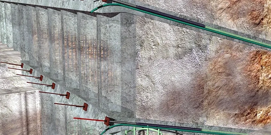
The most frequent mistake we see in LA excavations is treating tiebacks as a commodity item instead of a site-specific engineered system. A contractor grabs a generic bonded length from a previous job in the Valley, assumes it works in the Palisades, and ends up with creep failures during proof testing. That gets expensive fast. Anchor design here has to account for active wedge geometry behind shoring walls, passive resistance in the bond zone, and the seismic demand that ASCE 7 imposes on restrained structures. We run the load-transfer analysis for both temporary and permanent anchors, check the unbonded length against the failure plane, and verify that the bond stress doesn't exceed what the surrounding soil or rock can sustain. When the stratigraphy gets complicated—interbedded sandstone and claystone, for instance—we often correlate anchor capacity with data from CPT testing to refine the grout-to-ground bond values before finalizing the design.

A properly designed anchor isn't just a steel tendon in grout—it's a load path that must remain intact through 1.5 times the design seismic displacement.

Methodology and scope

The difference between anchoring in the stiff Pleistocene gravels of the Elysian Park area versus the decomposed granite found in the foothills above La Cañada Flintridge is night and day. In the gravels, we typically design for high bond stresses and short bond lengths, but the real challenge is drilling through cobbles without losing the hole. In the decomposed granite, bond stress is lower but the rock mass is more predictable for tendon installation. Our approach uses both active prestressed anchors—where we lock off at 120% to 133% of design load to control wall deflection—and passive anchors that engage only when the soil mass moves. The design load testing verifies the ultimate bond capacity, and we document the apparent tendon free length from the load-elongation curve to confirm that the unbonded length is clear of the failure plane. For projects where the shoring wall also carries structural loads, we integrate the anchor design with the retaining wall system analysis to ensure compatibility between anchor stiffness and wall bending moments.
Active and Passive Anchor Systems for Excavation Support in Los Angeles
Technical reference image — Los Angeles

Local geotechnical context

Southern California's combination of seismic activity and expansive dry-wet cycles creates a risk profile that generic anchor designs don't address. When a retaining wall is restrained by prestressed anchors, a seismic event can impose additional tensile forces well beyond the static design load—and if the bond zone sits in clay that softens after winter rains, the anchor loses capacity precisely when the wall needs it most. We've investigated failures in the Santa Monica Mountains where anchor heads pulled through the wale during a moderate earthquake because the unbonded length was too short to accommodate the dynamic soil displacement. Our design protocol explicitly checks the anchor elongation capacity against the wall movement required to mobilize passive resistance in the retained soil. For hillside cuts in the Hollywood Hills and similar terrain, we also address the risk of progressive anchor corrosion in pyritic shale by specifying Class I protection and testing the ground resistivity before selecting the tendon system. A slope stability analysis often runs in parallel to confirm that the anchored wall provides the global factor of safety needed under both static and pseudostatic conditions.

Need a geotechnical assessment?

Reply within 24h.

Email: info@geotechnicalengineering1.com

Reference parameters

ParameterTypical value
Design methodLimit equilibrium (active/passive wedge), finite element for complex geometry
Anchor typeBar tendons (≤ 150 kip), strand tendons (≥ 100 kip), hollow bar for collapsible soils
Bond length verificationLoad-transfer method per PTI DC35.1; pullout capacity correlated with SPT N60 or CPT qc
Proof testing acceptanceCreep rate < 2 mm over 10-min hold at 133% DL per IBC Section 1810
Seismic load conditionASCE 7-22 Section 11.8; 1.5 factor on anchor force for soil-structure interaction
Corrosion protectionClass I (double encapsulation) for permanent anchors; Class II for temporary (≤ 24 months)
Typical unbonded lengthMinimum 15 ft or extending 5 ft beyond critical failure surface

Other technical services

01

Tieback anchor design for soldier pile walls

Complete design package including tendon selection, bond length calculation, unbonded length geometry, and wale connection details. We provide the sealed calculations required for LA Department of Building and Safety plan check submission.

02

Proof testing and performance verification

On-site load testing with calibrated hydraulic jacks, dial gauges, and electronic load cells. We document the load-elongation curve for every anchor, compute the apparent free length, and evaluate creep compliance against IBC acceptance criteria.

03

Rock anchor design for hillside foundations

Design of high-capacity rock anchors for resisting uplift and lateral loads on hillside structures. Includes bond zone evaluation in fractured rock, grout mix design for variable groundwater conditions, and coordination with the structural engineer for anchor head embedment.

Reference standards

IBC 2024 Section 1810 — Anchors and Tiebacks, ASCE 7-22 Chapter 11 — Seismic Design Criteria for Structures with Restrained Earth Pressures, PTI DC35.1-14 — Recommendations for Prestressed Rock and Soil Anchors, ASTM A722 — Standard Specification for High-Strength Steel Bars for Prestressed Concrete (tendon material), Caltrans Standard Specifications Section 51 — Soil Nailing and Tieback Anchors

Common questions

What is the difference between active and passive anchors, and which one does my project need?

Active anchors are prestressed during installation—we tension the tendon against the wall and lock it off at a specified load, typically 120-133% of the design load. This controls wall deflection from the start and is essential for urban excavations adjacent to existing buildings. Passive anchors are not prestressed; they only develop resistance when the soil mass moves enough to engage the tendon. You'll see passive anchors used in soil nail walls and some slope stabilization systems. The choice depends on allowable wall movement: if you can't tolerate more than half an inch of lateral displacement, active prestressed anchors are the right call.

How long does anchor installation and testing take on a typical LA project?

For a mid-size excavation with 30 to 50 tieback anchors, installation usually runs 7 to 10 working days assuming normal drilling conditions. Proof testing adds about 15-20 minutes per anchor once the grout reaches the specified strength—typically 3 to 7 days after installation depending on the grout mix and ambient temperature. The full cycle from drilling to lock-off averages two to three weeks. Harder drilling in the crystalline basement rock of the San Gabriel foothills or dealing with buried debris in downtown LA can extend the schedule.

What does active/passive anchor design typically cost in Los Angeles?

The engineering design package for an anchored shoring system—including anchor load calculations, bond length determination, unbonded length geometry, corrosion protection specification, and the sealed calculation package for plan check—runs from US$1,020 to US$3,280 depending on the number of anchor rows, the complexity of the stratigraphy, and whether a performance test program is required. This covers the design only; installation and load testing are separate line items from the drilling contractor.
Location and service area

We serve projects in Los Angeles and surrounding areas.

View larger map